Shape Maker quality control tools.
In general almost every CAD, which is support free form NURBS surfaces can be used for the hull lines design.
Very often it depends from CAD price level and functionality for NURBS modeling.
Even mechanical CADs can be used for that. It’s may be OK if it is preliminary lines design.
But when necessary to make something more precise, it will take lot more time,
and finally you will not get acceptable result. Problem is in a poor functionality
for lines quality control in most of universal CADs.
Several important issues we have to take into account when we work with ship surface modeling:
- In ship design we work mostly with cross sections like frames waterlines and buttocks.
Most of the constriction elements connected to shell along such lines and it’s very natural
for engineer to check surface quality by checking cross sectional lines.
- Big scale of the models. Ship surface have usually much bigger size compare
to for example car or airplane. Big scale require more precise work with fairing
of the surface and follow many different initial data at same time.
- Technological aspects of the hull fairing. During production at workshop there
is a lot of bended elements like shell plates and profiles. Pure faired surface
will create troubles for bending and welding.
- Time factor. Ship design is mostly like tailor made product.
Every ship is different for another. Usually all design process takes several
months and hull lines should be ready as soon as possible.
- Economical aspect. If right faired surface will save for ship
owner just few liters of fuel in hour it can be quite a lot in total operation time.
- Esthetic's aspect. From long human history ship design was always like an art.
Every ship owner expect to have a nice ship with perfect hull shape, but not ugly
container for some equipment inside. In case of yachts it is one of the most important questions.
Many years we use Shape Maker for production lines fairing.
It was developed from beginning for ship design and in
close cooperation with ship designers. I would like to
show quality control functionality of this software.
Shape maker tools for surface quality control.
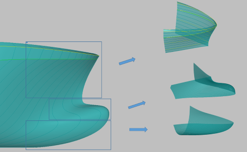
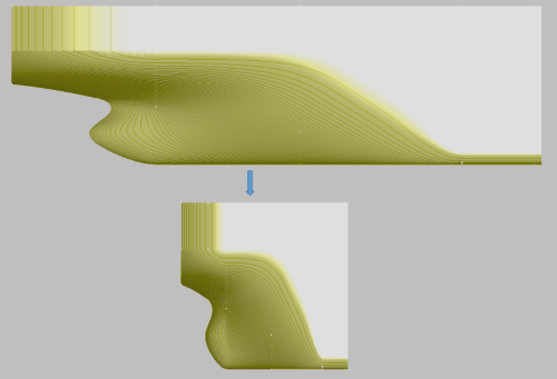
1. Dynamic control volume. Sometimes it is very difficult to check waterlines
in bulbous bow area. Many of them crossing each other and looks like big mess
of lines. In Shape maker user can defined volume for visualization.
All objects outside of this volume will be hidden. Additionally user can set up how
many sections like frames, waterline and buttocks should be presented inside this volume.
It help to quickly check any local shape's areas very precisely.
Another control volume option help to check cross sections line by line.
User can set up control volume for example for one frame spacing in deep and shift
it in deep for same distance. It help to check every cross section very easy and do
modification if necessary.
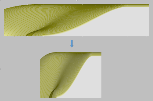
2. Old, but very efficient method for check hull lines quality is to look along line
almost in the drawings plane. It help to see all line's defects. This method was used
before computers and even now some designers, who trust only his own eyes, use it.
Analog of this in Shape maker - scaling view. Model can be scaled in one direction.
It give a better overview. For example if we work with long and narrow shape, like a
NACA profile, it is almost impossible to check how well this shape. Compressed view
show all defects. If lines will look's OK in compressed view it means in real scale
everything should be OK. Model in Shape maker scaled only for visualization. All coordinates,
dimensions not scaled and user can work in scaled view like normal view. This option very
useful for check and modification of surfaces in connection to flat side and flat bottom.
Very often it is almost impossible to check progress of building frames in connection to
flat side. So many lines comes almost to the same point. In compressed view it is much easy
to control and edit such areas. If it will look's good in compressed view it will be much
better in real scale. To resume - it is like a microscope for designer.
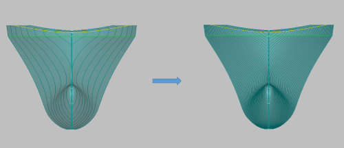
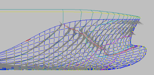
3. Visualization of curvature. Most of the systems have more or less same option.
In Shape maker shown radiuses of the curvature. It help to see all areas where
there is some local flatness areas. This is most important for production. Radiuses
of curvature dynamically updated together with frame sections during shape modification.
It give for user good impression how to change shape.
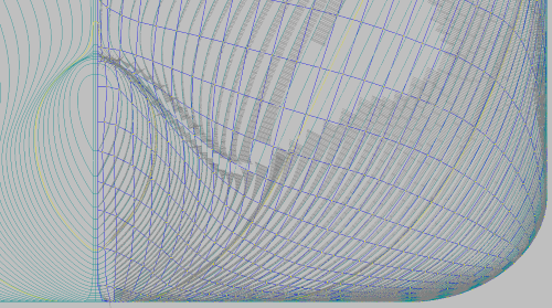
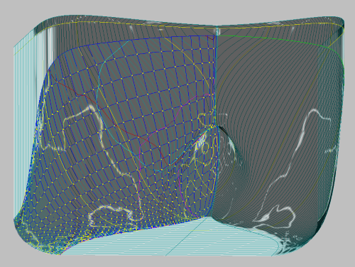
4. Even if we use surface for hull definition, we operate with frames,
waterlines and buttocks. Most of the inertial structure details based
on this sections. It is very important for designer to control shape
of such cross sections. Shape maker have possibility for dynamic visualization
of the inflection lines on the surface - lines where frames, waterlines and buttocks
change curvature direction. If frame crossing inflection line several times it means
frame has unnecessary bumps and it must be fixed. Infection lines indicate areas with
problems, and dynamically updated when used change shape. Additionally Shape maker have
visualization of the inflection lines for Gaussian curvature. It show an areas where
Gaussian curvature change direction.
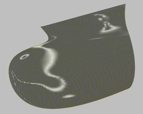
5. Shaded Gaussian curvature visualization help to check surface more precisely.
Curvature picture dynamically updated during surface modification process.