The practical principles of modeling ship surfaces with the NURBS.
NURBS-based representation of curves and surfaces has already become a standard of computer
modeling for many industries. Since 2000 the leading producers of CAD systems for shipbuilding
also use this standard for a ship surface definition.
NURBS-based representation gives such wide opportunities for modeling as no other means does and,
at the same time, NURBS has a series of features creating difficulties for understanding by the user.
It is a mechanism which controls the shape of curves and surfaces that a user faces at first modeling
with the NURBS. Traditionally, in all previously existing lofts methods, control of the shape of curves
and surfaces was carried out by defining points through which there passed a required curve or a surface.
In a case with NURBS the curve passes only through finite points of a reference polygon.
The shape of a curve will be defined by the shape of the reference polygon but to make a curve
or a surface pass through the given point auxiliary conditions are required.
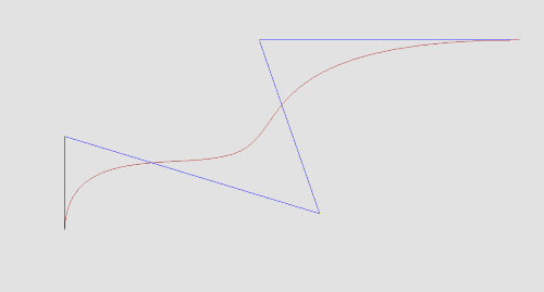 Nurbs curve example
During a long time the basic method of modeling a ship surface was a method of defining a grid of lines
on this surface. Various mathematical models were used as the mathematical representation of curves.
The most widespread model was a spline, which is analogous to a flexible spilling batten.
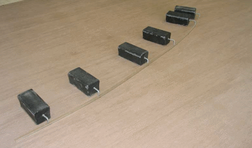 Spline
It was a grid of intersecting lines that determined a ship surface. Frames, waterlines and buttocks,
generally, were used as the lines. If during the operation with the surface there arose a necessity of
deriving coordinates of whatever point of the surface, the algorithm for calculation of the given point
was started depending on the shape of adjacent lines. Advantages of the given method include operation of
the user with lines which are natural for a ship constructor. Disadvantage of this method is the absence of
an analytically continuous (on tangents and curvature) surface.
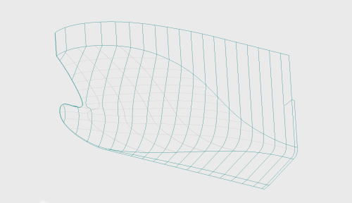 Grid of lines on hull surface
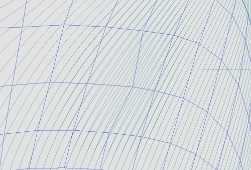
Notwithstanding the fact that NURBS-based representation of a ship surface meets the requirements
of analyticity and smoothness, the absence of possibility of controlling the shape of the surface by
means of direct modification of frames, waterlines and buttocks may become a major problem for a novice
user. Besides, as a rule, a NURBS surface is visualized as a set of lines of equal parameter which hardly
explain the shape of the given surface to the user. Therefore, many NURBS modellers include a method of
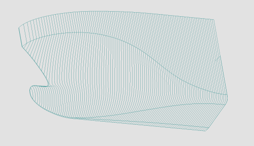
shaping a surface which passes through a set of cross sections (Cross sectional design). Unfortunately,
this method is not always applicable in case of a ship surface since it is impossible to describe intricate
contours, as for example, a bow bulb.
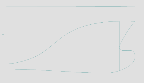 Not correct patches splitting in case of using "Cross sectional design"
One of solutions of this problem can be the possibility to dynamically display the deformation
of sections while editing control points of the surface. The user will control the shape of the
surface by moving the control points of a polyhedron and thus the user can see dynamic deformation
of sections.
 Frame sections local modification by control point
Unlike aviation or automotive industry where the shape of the hull is developed and optimized during
a long time, the terms of developing a surface in shipbuilding are very tight and in this case the optimum
division of the surface into patches becomes of high importance for construction of a NURBS-based ship surface.
While dividing the surface into patches, it is necessary to take into account a series of mathematical features
of curves and surfaces. Based on a long-term experience of the NURBS-based modeling of ship surfaces it is possible
to summarize the following principal requirements for dividing a surface into patches:
- Usage of degree of NURBS surfaces is not higher than the third degree. The higher degree gives an additional
smoothness of a surface and at the same time increase a modification area of the surface at correction of one
control point. Thus, the property of local surface modification is lost and there occurs a necessity of increasing
the number of control points.
- Obligatory splitting into separate patches of the surface between knuckle lines. Usage of mathematical NURBS
properties for creation of knuckles inside the surface patch is possible, but time consuming for control and is
practically not supported by many systems if it is necessary to transfer surface data from one system to another.
- Obligatory definition of flat side, flat bottom patches and patches of ruled surfaces allows to effectively
controlling the shape of these lines. Without segmentation into separate patches of the surface it is practically
impossible to obtain a correct line of a flat side or bottom only by modification of control points of the surface.
- The NURBS has a limitation of the number of boundary lines of the surface patches (usually three or four)
can be avoided by cutting-off the surfaces. Thus, the modeling surface is extended beyond the boundaries of the
modeled area and cut off along these boundaries.
- It is necessary to avoid division of smooth surfaces into separate patches. Joining of such patches, as a rule,
is performed only by the first derivative and does not result in required smoothness. Sections of the surface in
this region will not look smooth enough even visually. Only in case of radial conjugation of the surfaces the
joining is admissible and looks quite natural, in this case it is not necessary to maintain the condition
of continuity of the second derivative.
- Difficulties in modeling the shape of the surface patch corners can be avoided only by changing the boundary
lines. Control points inside the surface cannot practically affect the entrance angles of the surface patch in
area of the corner point.
Observing the above said requirements will allow avoiding many problems at modeling, to decrease time and
increase quality of the surface.
 Example of the correct surface subdivision
The quality of modeling a ship surface is one of the major factors for more accurate modeling of ship structures,
reduction of time, improvement of the hull assembly and welding quality that, in the long run, results in significant
decrease of building expenses. Thus, for example, the bended shell plates are most time-consuming parts of the hull
in the production and assembly. The quality of the shell plates directly depends on the quality of the ship surface.
In case of poor-quality of the ship surface and plate developments the errors, as a rule, are discovered only at assembly,
therefore, the production workers have to add extra material to edges of the shell plates and to trim them on-site during
assembly. This process requires a large amount of time and completely degrades the mounting and welding quality.
In the long run, the costs on elimination of defect can considerably exceed the costs on modeling. Shell plates without
extra material are considered to be optimal, but in this case the quality of the ship surface should be faultless.
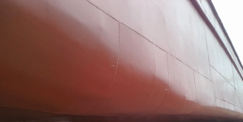 Not well faired surface
Therefore, control of the surface quality is one of the most important constituents in any ship surface modeling system.
The quality of surface directly depends on control tools in the system. Until recently the quality of a ship surface was
examined visually on the hull sections plot on a large scale and this it was a time consuming process. It was necessary
to plot, make modifications and plot once and again. In many NURBS-based state-of-the-art systems there exist the tools
for control surface based on visualization of a Gaussian curvature. It is not always applicable in case of a ship. Sometimes,
the ship surface, quite acceptable by the Gaussian curvature, leads to inadmissible bends of structural sections of the hull.
Thus, while modeling the surface the probability of errors is augmented and the quality is degraded. The same refers to
visualization of rendered surfaces. The rendered surface always looks much better than it actually is.
It is possible to enumerate some of the principal tools for control of the ship surface quality which make
it unnecessary to constantly print the drawing on paper:
- Visualization of a Gaussian curvature. Despite of ambiguity and non-demonstrativeness of the ship surface
representation it is possible to reveal problem zones.
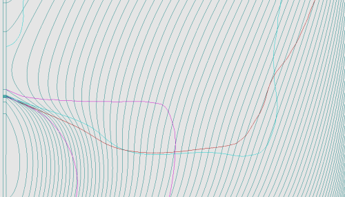
- Visualization of radii of curvature of the curves, sections and surfaces. Presently, it is one of the principal
control tools for many ship-building systems. Visualization of graphs of the radii of curvature
(instead of curvatures) allows controlling the most problematic areas of the curves, i.e. regions with a curvature
which is close to zero.
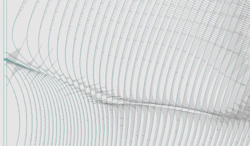 Frames radii of curvature visualization
- Visualization of inflection points of curves, inflection lines of surfaces and sections.This allows to more graphically
imagining the shape of the surface, the law of variation of the shape of the surface patches. It shows the surface problems
even between the surface sections.
 Inflection lines visualization for frames waterlines and buttocks
Application of the surface quality control tools mentioned above allows to completely avoiding printing the drawings on paper, to greatly reduce the modeling time and considerably increase the quality of a modeled surface.
Summarizing the aforesaid it is possible to distinguish some the principal stages of designing a ship surface:
- The analysis of the shape of a modeled surface and selection of segmentation into patches. It is a very important factor
while creating a surface. The modeling time and quality of a surface depends on optimality of division of the surface into patches.
- The definition of the surface patches with a minimum set of control points, approximation of the shape of a surface to the source
data and allocation of the control points. Your idea of the shape of a surface, if the hull is designed “from scratch” or the lines
of an initial body lines drawing, or the offset table points can be taken as the source data.
- increase in amount of the control points, definition of inflection lines on frames, waterlines and buttocks, more exact approximation
to the source data. At this stage it is necessary to make efforts for minimizing the deviation from the source data and at the same time
defining correct arrangement of the inflection lines, i.e. eliminating errors, which exist in the initial source data.
- Minimization of the curvature of waterlines, frames and buttocks. At this final stage it is necessary to achieve the acceptable
smoothness of lines of the sections. It is a repetitive process and, generally, a small displacement of control points is enough for
meeting the smoothness requirements. During the smoothing process it is also necessary to control position of inflection lines.
Following this technique has modeled more than 300 surfaces of the hulls of different types of the vessels. The most of them were used
at construction of the vessels and have proved to be the high quality surfaces. This paper is only a small part of accumulated practical
experience, but it also can be useful both for novice users and specialists in modeling with the NURBS.