NC Maker technical description.
NC Maker questions and answers.
Q&A->How to make new postprocessor.
About NC Maker.
Main window.
Menu.
File.
File->Open.
File->Save.
File->Print.
File->SaveAll.
File->Insert NC.
File->NC of folder.
File->DXF of folder.
File->Format load.
File->Code editor.
File->View.
File->Reports.
File->Measuring tool.
File->Material.
File->Options.
File->Options->Screen
File->Options->Save
File->Options->DXF
File->Options->Path
File->Options ESSI.
File->Options EIA.
File->Default Options.
File->Statistics.
File->Check NC file.
File->Language.
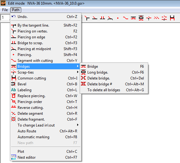
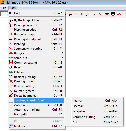
Path.
Path->Undo.
Path->By the tangent line.
Path->Piercing on vertex.
Path->Piercing on edge.
Path->Bridge to scrap.
Path->Piercing at midpoint.
Path->Piercing.
Path->Segment with cutting.
Path->Bridges.
Path->Bridges->Bridge.
Path->Bridges->Long bridge.
Path->Bridges->Delete bridge.
Path->Bridges->Delete bridge#.
Path->Bridges->Delete all bridges.
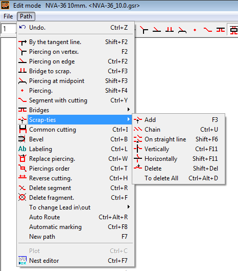
Path->Scrap-ties.
Path->Scrap-ties->Add.
Path->Scrap-ties->Chain.
Path->Scrap-ties->On line.
Path->Scrap-ties->Vertically.
Path->Scrap-ties->Horizontally.
Path->Scrap-ties->Delete.
Path->Scrap-ties->Delete All.
Path->Common cutting.
Path->Bevel.
Path->Labeling.
Path->Replace piercing.
Path->Piercings order.
Path->Reverse cutting.
Path->Delete fragment.
Path->Change LeadIn\Out.
Path->Auto route.
Path->Auto marking.
Path->New path.
Path->Plot.
Path->Nest.
Release and development history.
PDF/NestMakerPresentation.pdf
NC Maker questions and answers.
In this part we will try to collect questions and answers from our customers.
To top.
Q&A->How to make new postprocessor.
Easiest way to make new postprocessor is to use prototype CNC program.
The CNC program should contain all necessary codes: marking and cutting sequence,
text printing commands, if it will be used in new postprocessor. Better if CNC contain also inner and outer
contours of cutting sequence.
Load the example CNC program into NC Maker
and open File->Options ESSI, if the example of ESSI codes.
Example file name – 851501.mpg. NC Maker collect ESSI codes for new postprocessor into codes table.
What is necessary to do in most simple case is to give a new postprocessor name instead of text "Unknown format ESSI" and save it.
After that new postprocessor will be available in converting menu.
If it necessary we can replace information in file header. NC Maker recognize header text like text, but we need to put into header CNC file name.
Instead of "%||PO851501(8515014.MPG)" we can add text "%||PO$NAME$($FILE$)". Symbol || means next string. In every new CNC programm converted
by our postprocessor we will have CNC program name and file name and extension.
Following variables can be added into header or footer sections:
$NAME$ - CNC file name,
$FILE$ - CNC file name and file extension,
$EOF$ - End of file symbol,
$SPEED$ - cutting speed,
$A$ - gross plate length,
$B$ - gross plate width,
$EKW$ - cutting allowance in mm,
$EKWI1$ - cutting allowance in 0.1 mm,
$EKWI2$ - cutting allowance in 0.01 mm.
To top.
About NC Maker.
NC Maker is simple and powerful CNC programming tool for cutting machines.
Main features:
1. Import DXF file with parts layout and converting them into any CNC cutting program.
2. Read, check any modify any types of CNC program.
3. Automatically create new postprocessor based on cutting program example.
4. Converting CNC files one type into another.
5. Auto routing function for marking and cutting sequence.
6. Powerful tools for manual editing of cutting programs.
7. Step by step cutting sequence simulator.
NC Maker has full support for any types of cutting machines. Any type of cutting,
marking and printing tools can be used for NC programming, including beveling. NC
Maker supported standards:
ESSI ( ISO 6582 )
EIA ( RS-274-D )
G-code ( ISO 6983, DIN 66025, PN-73M-55256, PN-93/M-55251 )
To top.
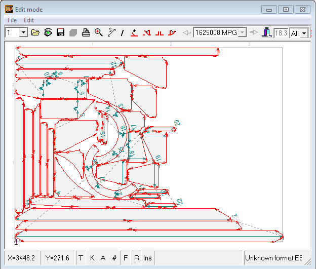
Main window.
 List of important fields of NC Maker main window:
1. NC program step scale factor.
2. On/Off text information on nesting layout.
3. On/Off part's edges with beveling.
4. On/Off inner contours detection during importing DXF files.
5. On/Off grid visualization.
6. On/Off gray coloring of the parts inner space.
7. On/Off marking lines collision control.
8. On/Off insert mode for NC editing.
9. Help string.
10. The path to an open file.
11. List of an open files.
To top.
Menu.
NC Maker main menu consist of two items:
File - contain all necessary commands and options for file
operations, converting and etc.
Path - contain commands for making and editing cutting
programs
To top.
File.
File menu has following options:
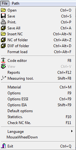
To top.
File->Open.
Several different files can be open by this command:
Nests group (GSR) – file from Nest Maker software contains nesting layouts for one
thickness and material quality.
DXF (NC) – DXF file contains a NC marking and cutting sequence.
DXF (Nest) – DXF file contains a parts layout (just plate parts).
Different ESSI and EIA CNC programs can be recognized by choosing suitable converter
from the converters list.
Note! Only one GSR file can be loaded at same time, but several DXF or CNC files
can be selected and processed at same time.
To top.
File->Save.
Type of saving files depends form what type of file was open:
Nests group (GSR) – file can be saved as GSR. If DXF or CNC converter selected -
only current nest will be saved into corresponding file format.
DXF or CNC - file file can be saved like DXF or converted by selected CNC converter.
To top.
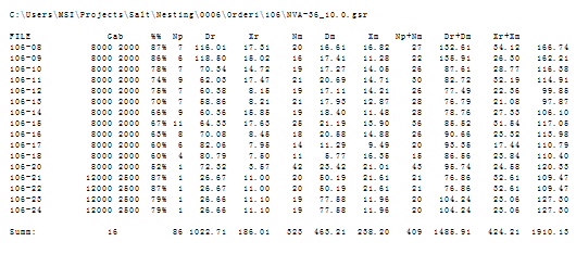
File->Print.
Nest layout can be printed onto selected printer or PDF. Printing options can be
chosen in following menu:
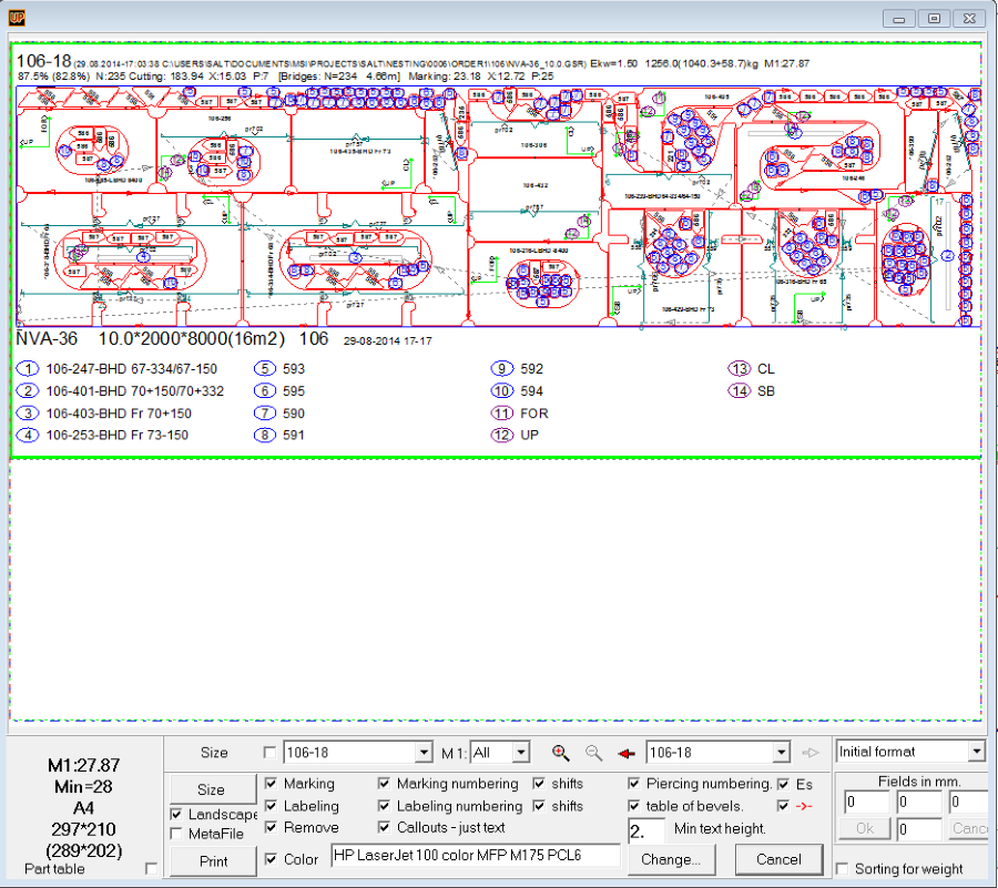
The most important information:
NC file name and extension
Printing date, time and path to the file
Data about cutting process. Cutting length - 47.51m, rapid traverse 12.54m and 5
piercings.
Data about powder marking process. Marking length - 17.78m, rapid traverse 12.45m
and totally 16 lines.
Scrap ratio, parts weight and plate weight enclosed in brackets.
Scale of printed cutting map.
To top.
File->SaveAll.
All nests in GSR or all loaded files will be converted and saved into selected file
format.
To top.
File->Insert NC.
By this command user can join one more CNC programs described in different file
formats.
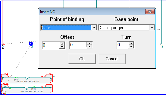
After selecting CNC file for insertion, user can select insertion point, begin of
cutting point, necessary shifts on inserted CNC program and also rotation.
To top.
File->NC of folder.
This command will generate CNC programs for all GSR files in current working folder.
Usually it used for generation of all CNC for one building block or unit.
To top.
File->DXF of folder.
This command will generate DXF NC sketches for all GSR files in current working
folder. Usually it used for generation of all DXF sketches for one building block
or unit.
To top.
File->Format load.
Files *.format contains converter description commands. By loading this files user
will get new postprocessor for converting files or generation new NC. This option
provides exchange possibility between different customers.
To top.
File->Code editor.
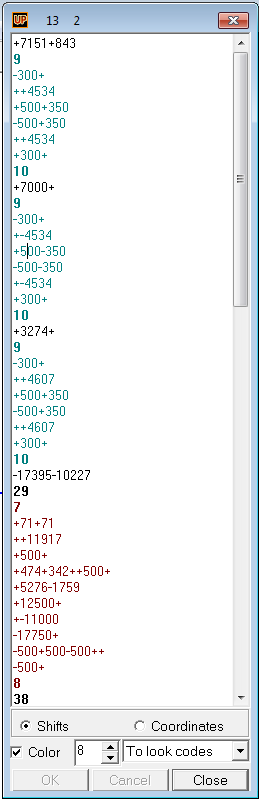
Code editor show all CNC commands in the text window in according with selected
type of postprocessor. The following colors are used for marking different type
of NC code:
Cyan – marking sequence,
Dark red - cutting sequence,
Blue – braking codes,
Grey – comments,
Red – End of NC data codes,
Black – rapid traverse and other codes.
User can change type of postprocessor for visualization, switch between absolute
an relative coordinates of NC. Selected string in text window will be shown in graphics
window by green arrow. By moving up and down cursor in text window user can simulate
cutting sequence in graphics window.
To top.
File->View.
This tool has possibilities similar to Code editor,
but the difference is – viewer text window shows original codes of opened NC file,
and you cannot edit them in this mode. Colors and signs are the same as for
Code editor.
To top.
File->Reports.
Reports command create all necessary reports for cutting process on the Yard.
To top.
File->Measuring tool.
By this command user can measure distances on the nest.
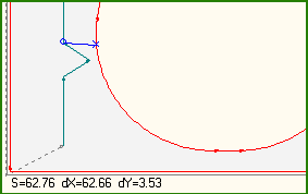
It gives - total distance (S) and distances in X (dX) and Y (dY) axis between two
points. Points for measuring have to be on line or on the edge of plate. NC maker
will snap to the nearest vertex or point on line. If vertex is selected, it will
be marked by blue circle “o”, and if just a point on line it will be marked by blue
“x”.
To top.
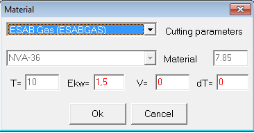
File->Material.
Parameters like material type, kerf compensation, density and cutting speed can
be modified by Material command.
To top.
File->Options.
Dialog Options contain most of important settings for NC Maker.
To top.
File->Options->Screen.
Tab Screen responsible for the presentation of different information on the main
window.
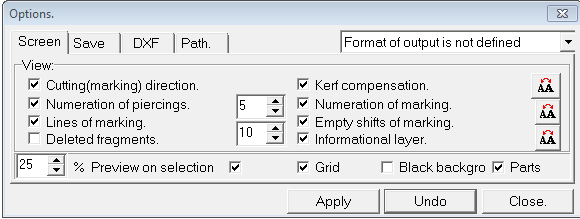
Most important features are:
On/Off Cutting/marking direction - visualization cutting and marking direction,
On/Off Numeration of piercings - give a number for each piercing point,
On/Off Lines of marking - show marking lines,
On/Off Deleted fragments - show deleted elements of CNC program after editing,
On/Off Kerf compensation - show side of kerf compensation for cutting lines,
On/Off Numeration of marking - show number of each new marking line,
On/Off Empty shifts of marking - show rapid traverse lines,
On/Off Information layer - show text information - parts names, connected parts
names, frame numbers and etc.,
On/Off Grid - show grid lines,
On/Off Black background - background color - black on white, white on black or use
default Windows background color,
On/Off Parts - show inner space of parts by gray color,
On/Off % Preview on selection - show previews of NC when file open dialog.
Additionally there is several possibilities to change font and color for text on
NC.
To top.
File->Options->Save.
Tab Save responsible for setting before saving NC programs.
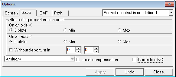
Most important features are:
- O plate - Minimum of gross plate for X and Y,
- Min - Minimum of the nest for X and Y,
- Max - Maximum of the nest for X and Y,
On/Off Without moving in - keep cutting tool in same position if On,
On/Off Local compensation - kerf calculation,
On/Off Correction NC - run correction dialog to set up some specific NC parameters.
Previous parameters from postprocessor will be ignored.
User can also defined additional shift by X & Y from selected cutting tool position.
To top.
File->Options->DXF.
Tab DXF responsible DXF import/export setting.
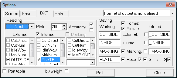
The DXF tab divided on two parts: - Reading:
Contain setting for correct reading NC or Nest from DXF.
In list user can choose Layer with plate geometry description.
Accuracy determinate DXF approximation precision in 1/1000 mm value (1-20000).
By choosing Layer in External box user defined default parts outer contour.
By choosing Layer in Internal box user defined default inner contour.
Marking box is responsible for Layer with marking information.
- Saving:
Contain setting for export NC programs and sketches into DXF.
On/Off Picture - output sketch with more readable text.
in boxes user can define own layer name for inner, outer, marking and plate information.
Deleted fragments can be also exported to DXF in separated layers.
On/Off List - output sketch in scale 1:1 with rapid traverse statistics.
On/Off Shifts - output inlet/outlets into DXF sketch.
To top.
File->Options->Path.
Tab Path responsible for new route definition settings.
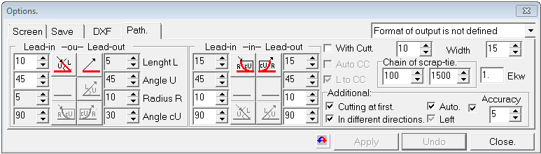
User can define inlet/outlet geometry for outer contour and inner contours separately.
All dimensions in mm, angles in grad.
On/Off With cutt. - user can choose if necessary to move from part to another with
cutting tools switch on.
On/Off Cutting at first - user can choose if necessary to start cutting before marking.
On/Off Auto - automatically making rout for inner contours when outer contour for
part defined.
To top.
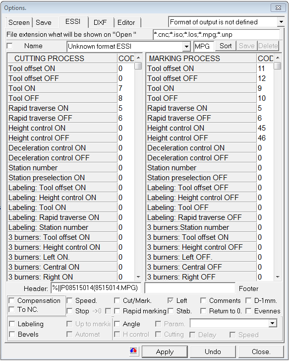
File->Options ESSI.
Options ESSI responsible for ESSI settings of the current postprocessor.
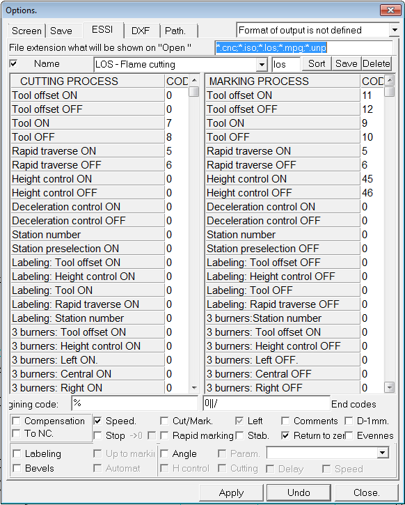
The dialog consist of following parameters: File extension will be shown on
Open
- list of available extension for reading ESSI files.
On/Off Name - make postprocessor available for Save
command. Another words only active postprocessors will appear in list when user
save program.
List of available postprocessors. When user choose postprocessor from the list,
all settings will be updated in accordingly.
Postprocessor file extension.
Button Sort - sort of postprocessors list.
Button Save - save new postprocessor into ".format" file.
Button Delete - delete current selected postprocessor from list.
Cutting process codes - contain all necessary definition for coding cutting sequence
of CNC ESSI.
Marking process codes - contain all necessary definition for coding marking sequence
of CNC ESSI.
Header - additional information in begin of CNC file.
Footer - additional information in end of CNC file.
On/Off Compensation - allow programs calculation of the kerf compensation.
On/Off To NC - allow kerf compensation definition by ESSI commands.
On/Off Speed - include control cutting speed commands.
On/Off Cut/Mark - allow mix in CNC cutting and marking sequences.
On/Off Left - allow kerf compensation from left or right. If it's a gray color -
not control.
On/Off Comments - add CNC file information into CNC header.
On/Off D-1mm - make NC discrete step 1 mm.
On/Off Stop - Stop command after marking.
On/Off Stop - Stop command after marking.
On/Off Rapid marking - marking on rapid speed.
On/Off Stab. - marking lines high stabilization function.
On/Off Return to zero - move cutting tool to initial position after cutting is finished.
On/Off Evenness - add checksum for major byte ( used for paper type only ).
On/Off Labeling - allow printing text information by NC program.
On/Off Up to marking - all printing commands will be located in NC before marking.
Available only if "Labeling" is "On".
On/Off Angle - add high stabilization command before corner.
On/Off Param - if "On" beveling parameters will be set before corner loop if "Off"
after corner loop.
Special description file for current postprocessor (.SV) can be selected additionally.
On/Off Bevels - allow generate program with beveling information. In list of files
(.bvl) user have to choose one of three cutting tools.
On/Off Automat - add to CNC commands (120, 121, 122, 123 ) for control of angles
and hihts of left and right cutting tools.
On/Off H-control - use high stabilization command before loops.
On/Off Cutting - use three cutting tools. if "On" beveling parameters will be set
before corner loop if "Off" after corner loop.
On/Off Delay - delay for switch on and rotation of the cutting tool.
On/Off Speed - reduce speed before loop for switch on and rotation of the cutting
tool.
Button Apply - save all changes in the postprocessor.
Buttons Undo or Close - keep the settings without changes.
To top.
File->Options EIA.
Options EIA responsible for EIA settings of the current postprocessor.
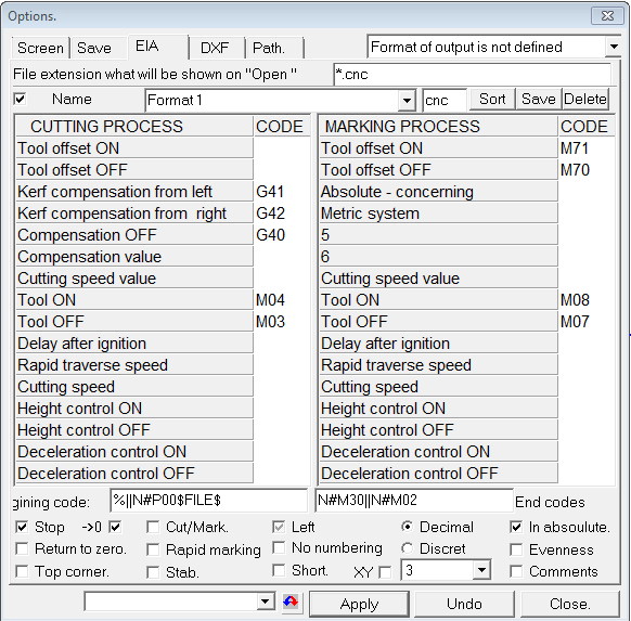
The dialog consist of following parameters: File extension will be shown on
Open
- list of available extension for reading ESSI files.
On/Off Name - make postprocessor available for Save
command. Another words only active postprocessors will appear in list when user
save program.
List of available postprocessors. When user choose postprocessor from the list,
all settings will be updated in accordingly.
Postprocessor file extension.
Button Sort - sort of postprocessors list.
Button Save - save new postprocessor into ".format" file.
Button Delete - delete current selected postprocessor from list.
Cutting process codes - contain all necessary definition for coding cutting sequence
of CNC ESSI.
Marking process codes - contain all necessary definition for coding marking sequence
of CNC ESSI.
Header - additional information in begin of CNC file.
Footer - additional information in end of CNC file.
On/Off Stop - Stop command after marking with or without moving into 0 position.
On/Off Cut/Mark - allow mix in CNC cutting and marking sequences.
On/Off Left - allow kerf compensation from left or right. If it's a gray color -
not controlled.
On/Off Decimal - allow to use floating point format values in program.
On/Off In absolute - allow to use absolute or relative coordinates.
On/Off Return to zero - move cutting tool to initial position after cutting is finished.
On/Off Rapid marking - marking on rapid speed.
On/Off No numbering - disable string numeration in NC program.
On/Off Discreet - allow to use discreet step values in program.
On/Off Evenness - add checksum for major byte ( used for paper type only ).
On/Off Top corner - start program from top left corner.
On/Off Stab. - marking lines high stabilization function.
On/Off Short - allow to use short command notation.
On/Off XY - allow to set up number of digits for coordinates.
On/Off Comments - add CNC file information into CNC header.
All additional parameters can be added into (.sv) file and selected for current
postprocessor. Button Apply - save all changes in the postprocessor.
Buttons Undo or Close - keep the settings without changes.
To top.
File->Default options
This command will set default options in according of the current project settings.
To top.
File->Statistics
This command will calculate statistic information for current CNC program.
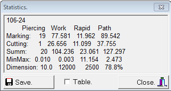
If several NC files loaded user can "On" Table and save statistics information for
all loaded NC into file with extension (.sta).
To top.
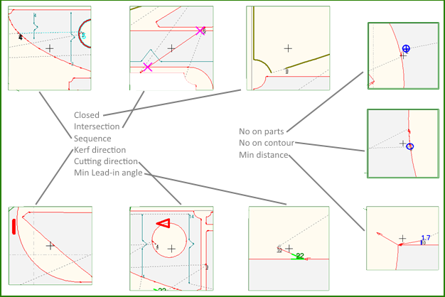
File->Check NC file
This command will show dialog for checking NC file.
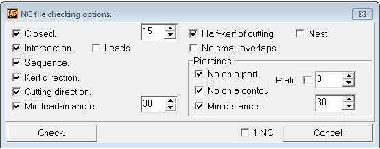
The dialog have several options:
On/Off Closed - checking for not closed contours.
On/Off Intersection - checking for intersections of cutting lines.
On/Off Sequence - checking for mixing cutting and marking sequence.
On/Off Kerf direction - checking for wrong kerf compensation direction.
On/Off Cutting direction - checking for wrong cutting direction.
On/Off Min lead in angle - checking for wrong lead in angle.
On/Off Half kerf of cutting - checking for half kerf cutting when common cutting
used.
On/Off No small overlaps - checking for small intersections.
On/Off No on parts - checking for piercings inside parts.
On/Off No on contour - checking for wrong piercings on contour of parts.
On/Off Min distance - checking for distance between piercing and contour.
Check can be done for one NC or for all loaded at this moment.
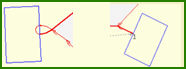
All detected problems will appear in resulting list.
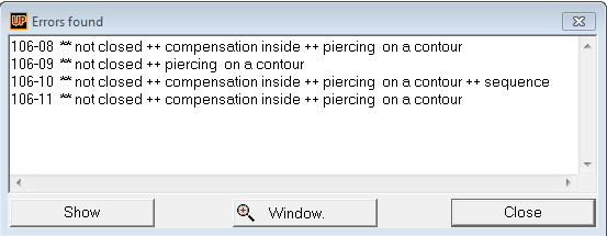
For visualization of detected errors it necessary click button "Show" or double
click on selected string. Button "Window" show zoom into area where problem detected.
Here is example for visualization of typical errors:
To top.
File->Language.
At this moment NC Maker available on English and Russian languages.
To top.
Path.
Path menu has following options:
All command for manual or auto routing collected in this menu.
To top.
Path->Undo.
Undoing previous editing operation. NC Maker has unlimited undo operations.
To top.
Path->By the tangent line.
This command is used for start cutting sequence with in-let by tangent line to part
contour. User need to click on part's point and select cutting direction. For not
closed contours only end points used.
To top.
Path->Piercing on vertex.
This command is used for contours node points. User need to click on part's node
point and select cutting direction.
To top.
Path->Piercing on edge.
This command is used for contours edges. User need to click on part's edge and select
cutting direction. It can be used for cutting and marking.
To top.
Path->Bridge to scrap.
This command is used for making bridge to scrap material to hold small parts position
on the cutting table. User need to click on part's edge and select cutting direction.
To top.
Path->Piercing at midpoint.
This command is used for making piercing exactly in middle of two node points. User
need to click on part's edge and select cutting direction.
To top.
Path->Piercing.
This command provide inserting piercing in any place on gross plate. After inserting
first point, cutting mode will switched on and user can make cutting sequence.
If insertion mode is on user can click on rapid traverse line and make new piercing
point.
To top.
Path->Segment with cutting.
This command provides inserting any configuration of the cutting polyline segment.
If endpoint of such segment comes to part contour, it is necessary to select direction
of cutting. If insertion mode is on, cutting segment will start immediately after
selection of rapid traverse line. Double click on rapid traverse line convert the
line to cutting segment.
To top.
Path->Bridges.
Bridges menu item collect all available operations with bridges. Bridges is most
common technique for cutting correctly small parts.
To top.
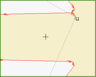
Path->Bridges->Bridge.
If part with no cutting route located close to another one with route, it's enough
just click on space between two parts to make bridge.
It is also possible to make a several bridges between two parts.
To top.
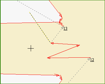
Path->Bridges->Long bridge.
Long bridge command create bridges between all parts crossing by defined line. By
clicking following tool bar user can choose inclined line, vertical or horizontal.
Beginning point of this line should start from existing cutting sequence.
Bridges between parts will be generated in according with cutting parameters settings.
To top.
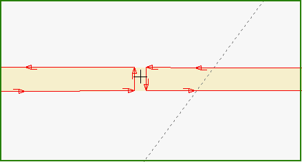
Path->Bridges->Delete bridge.
To delete bridge between two parts user need to click inside bridge body.
To top.
Path->Bridges->Delete bridge#.
To delete bridge between two parts user need to click inside bridge body. This command
similar to Delete bridge, but additionally
delete all cutting sequence after bridge.
To top.
Path->Bridges->Delete all bridges.
This command will delete all bridges in the current nest.
To top.
Path->Scrap-ties.
Scrap-ties menu item collect all available operations with scrap-ties. It's used
to fix position of long parts on the cutting table.
long and thin parts, can be easily deformed by hitting
during cutting process. Only scrap-ties can help to hold correct geometry for such
plate parts.
To top.
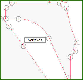
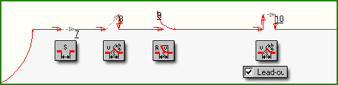
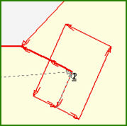
Path->Scrap-ties->Add.
By this command user can add scrap-ties on the cutting contour. Picture below demonstrate
available configuration of the scrap-ties:
To top.
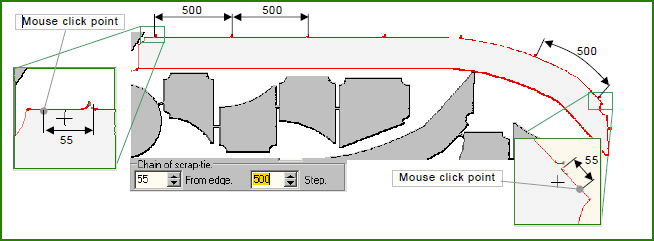
Path->Scrap-ties->Chain.
By this command user can add several scrap-ties on the cutting contour by equal
distance. User need to select begin and end points on the contour. Distance between
scrap-ties defined in File->Options->Path.
To top.
Path->Scrap-ties->On line.
This command works similar to Path->Bridges->Long
bridge. User need to define begin and end points for line. All parts crossed
by this line will have scrap-ties.
To top.
Path->Scrap-ties->Vertically.
User need to define begin and end points for vertical line. All parts crossed by
this line will have scrap-ties.
To top.
Path->Scrap-ties->Horizontally.
User need to define begin and end points for horizontal line. All parts crossed
by this line will have scrap-ties.
To top.
Path->Scrap-ties->Delete.
Delete scrap-ties by clicking on it.
To top.
Path->Scrap-ties->Delete All.
Delete all scrap-ties on current nest.
To top.
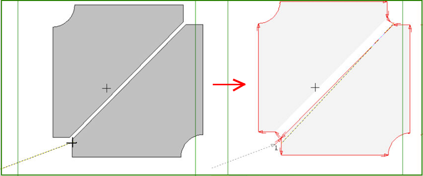
Path->Common cutting.
Common cutting command let user to make common cut line for parts joined by straight
edges. Before that part should be joined together by special commands in nesting
software. To make common cot line is necessary to click on part edge just before
common area. This part will be cutted first. Second part will be shifted on half
kerf distance from first one.
To top.
Path->Bevel.
CNC programs with beveling information can be generated only in ESSI file format.
To use EIA codes please use converting facilities from your cutting equipment software.
Beveling settings can be different for different type of cutting heals.
Settings for one cutting head:
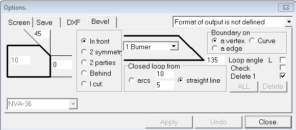
Bevel geometry can be chosen from menu. Bevels can be done from:
On/Off In front - this side
On/Off 2 parties - both sides not symmetrical
On/Off Behind - other side
Field with plate thickness available only for imported DXF files without thickness
information.
Boundary On: On/Off a vertex - end of beveling is a knuckle point close to clicked
edge
On/Off a curve - beveling for all clicked contour
On/Off a edge - beveling two clicked points on part contour
On/Off Check - beveled contours shown by blue color
On/Off Loop angle L - detect maximum angle for making loop
On/Off Delete 1 - delete bevels one by one
Closed loop from:
On/Off Arcs - arced loop
On/Off Straight line - triangle loop
Button ALL - add bevels for nest
Button Delete - delete bevels for nest
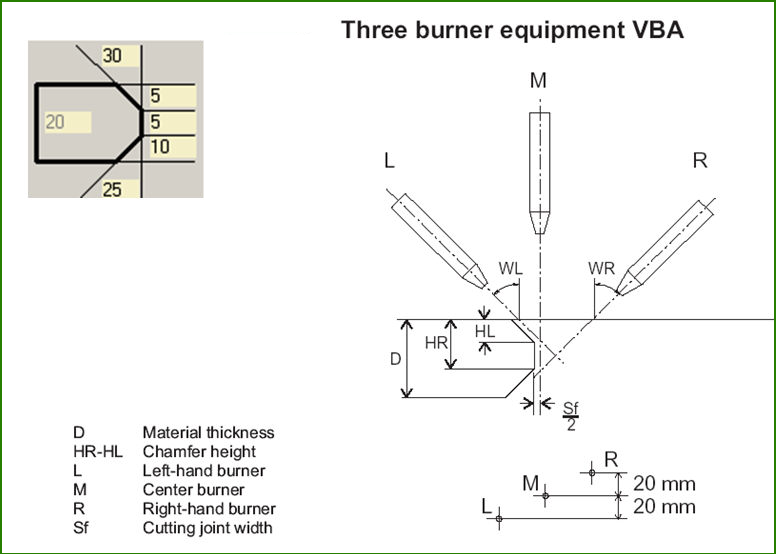
Settings for three cutting heads:
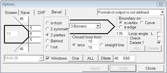
Most of settings are same as for one cutting head.
Additional parameters:
On/Off Windows - control process definition of windows on plate for setup and start
burning of cutting heads. Blue color areas show places where windows can be cut
for manual settings of the cutting parameters.
Window area:
With cutting route:
Route for cutting all windows can be set up for all together of add and delete one
by one.
Buttons One and All is used for make route for all windows or one by one.
Button Delete for deleting all windows routes.
To top.
Path->Labeling.
By this command user can add text labels for printing into CNC code.
Parameters of text for labeling:
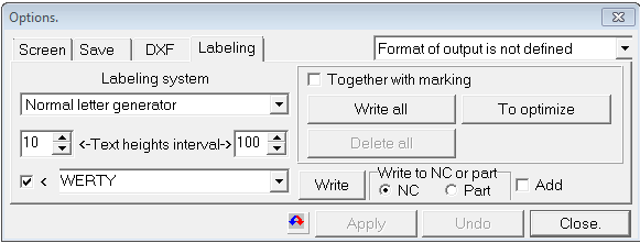
Labeling system:
Normal letter generator - inset printing text commands into CNC code.
UPEditor.fnt - insert text into CNC as marking lines.
Button Write all - write all text commands into CNC.
Button To optimize - run optimization of rapid traverse movement.
Button Delete all - delete all texts.
On/OFF Together with marking if it's On commands for buttons All write, To optimize,
Delete all expand to marking lines also. On/OFF Add - all text commands will be
added it end of NC file.
Text heights interval - describe minimal and maximal text heights. Write to NC of
parts:
NC - text will be added to CNC program only.
Part - text will be added as text on plate part ( if GSR file open only ).
To top.
Path->Replace piercing.
User can change position and geometry of early defined piercing point. After selecting
existing piercing point settings window will appear on the screen for changing piercing
geometry, if it necessary, then select new piercing position.
To top.
Path->Piercings order.
Marking, cutting and text printing sequence in CNCN program can be changed by this
command. First cutting or marking line should be selected, then necessary select
new codes sequence.
To top.
Path->Reverse cutting.
By this command cutting direction can be changed for part or group of parts connected
by bridges. if will affect outer contour and inner contours.
To top.
Path->Delete fragment.
By this command user can delete fragment of the cutting sequence between two node
points.
To top.
Path->Change LeadIn\Out.
By this command user can change LeadIN LeadOut for different elements of NC program.
This parameters can be changed for cutouts, outer contours, bridges, common cuts
or for all elements together.
To top.
Path->Auto route.
This command used for making route automatically for current nest or for group of
nests.
Parameter of the Option menu similar to File->Options->Path,
but some extra parameter add on the bottom of the menu:
On/OFF TXT - include printed text into CNC file
On/Off MRK - include marking sequences into CNC file
On/Off Size is more - make self cutting bridges for parts bigger than []x[]
On/Off For all NC - make NC for all nests in the list
Button To execute - run routing process.
To top.
Path->Auto marking.
Automatically make marking sequence for current layout.
To top.
Path->New path.
Delete all previous defined CNC codes. and keep only parts geometry.
To top.
Path->Plot.
Printing sketch for the photo-copying cutting.
To top.
Path->Nest editor.
Run nest editor for current layout.
To top.
NC Maker release and development history.
10.02.16 Auto route with beveling information implemented.
10.02.16 Extended EIA commands support added.
12.06.15 Nesting sketch template improved for part's list output.
16.05.15 New EIA postprocessor for Microstep cutting machine implemented.
10.03.15 Auto route with bridges between small parts only implemented.
18.02.15 Nesting sketches layers and colors for DXF file improved.
10.04.14 NC Maker new release now available.
15.03.14 User settings synchronization for project.
10.03.14 Self cutting bridges implemented for auto route function.
05.02.14 Nupas DXF parts import improved.
21.11.13 Link to Nupas-Cadmatic database via XML interface.
19.09.13 Inlet/outlet settings separated for inner and outer contours.
20.06.13 Changing cutting start point position implemented.
28.03.13 NC Maker new release now available.
10.02.13 Auto route function improved.
01.02.13 Auto route for all nests with the same thickness implemented.
To top.